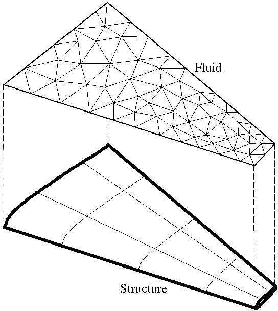
The prediction of many fluid/structure interaction phenomena requires solving simultaneously the coupled fluid and structural equations of equilibrium with an appropriate set of transmission (interface boundary) conditions. In many situations, the fluid and structure subproblems have different mesh resolution requirements and as a result, their computational domains have non-matching discrete interfaces (Figure 1). Converting the fluid pressure and stress fields at the fluid/structure interface into a structural load and transferring the structural motion to the fluid system can be performed in three steps:
In many applications, Step 1 can be performed once, in a preprocessing phase, by a computational geometry module. The MATCHER code discussed in this document is such a module. It outputs information that can be exploited to populate the data structures of a flow solver and a structural analyzer that are necessary for exchanging aerodynamic/hydrodynamic and elastodynamic data. Subsequently, Step 2 can be performed by elements of an accompanying library of subroutines that are callable from the flow solver and the structural analyzer. Finally, Step 3 can be performed either via any communication channel (for example, MPI) including I/O.
This document focuses on Step 1 and the MATCHER module.

Figure 1: Fluid Mesh (or Embedded Discrete Representation of the Wet Surface of the Structure) and Structure Mesh with Non-Matching Discrete Interfaces

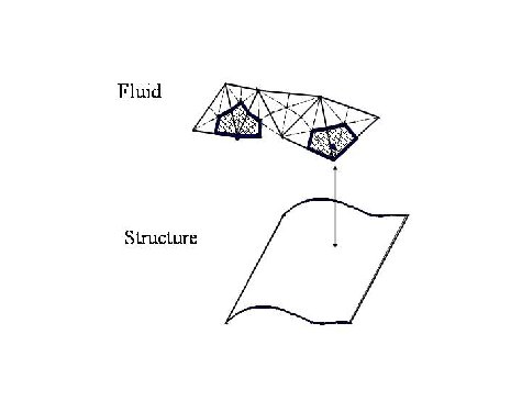
Figure 2: Pairing of Entities of the Structural Mesh and Fluid Mesh (or Embedded Discrete Representation of the Wet Surface of the Structure)
MATCHER requires (and accepts) the following (optional) input files:
fluid.mesh. This file, which can have any name, describes the unstructured mesh of the fluid domain.
It can be in the Sinus, XPost, or FieldView format. When written in the XPost
format, this file describes
the unstructured discretization of the fluid domain as well as the
boundary conditions. The latter are speficied as
element sets with the following conventions for naming the element
sets: “OutletMoving” for the moving outflow
boundary,“InletMoving” for moving inflow boundary, “StickMoving” for
the moving viscous wall boundary,
“SlipMoving” for the moving Euler wall boundary, “Symmetry” for the
symmetry boundary, “SlipFixed” for the
fixed Euler wall boundary, “StickFixed” for the fixed viscous wall
boundary, “InletFixed” for the fixed inflow
boundary, “OutletFixed” for the fixed outflow boundary, and “Kirchhoff”
for the internal surface suitable for computing the sound field using
the
Kirchhoff integral method. Among these element sets, only the following
ones
are acted upon by MATCHER: “OutletMoving”, “InletMoving”, “StickMoving”, and “SlipMoving”.
fluid.control. This file, which can have any name, is an optional file. By default, only the nodes
located on the “moving” surfaces of the fluid mesh are “matched” with corresponding nodes on the “wet”
surfaces of the structural mesh. However, the user can request either that some nodes located on the moving
surfaces of the fluid mesh be not matched, or that some nodes of the fluid mesh which are not located on
the moving surfaces be matched. The unified syntax for both cases is given below.
CNBC < +- > | <number of nodes>
|
<node number> |
|
<node number> |
|
| ... |
|
A positive number of nodes on the first line indicates that the following nodes are to be matched with structure nodes, in addition to the wall surface nodes. A negative number of nodes on the first line indicates that the nodes specified on the following lines are not to be matched.
structure.input. This file, which can have any name, is typically the AERO-S input file. Its content
and syntax are described in the AERO-S User's Manual.
structure.control. This file, which can have any name, is an optional file. By default, all the elements
listed in the structure.input file are processed by the matching program. However, the user can request
either that some elements listed in structure.input file be ignored, or that only a list of elements
specified in the structure.control file be processed by the matching code. Furthermore, two different
mechanisms based on elements and nodes, and which can be combined, are available for invoking
one or the other action. The syntax for all cases is given below.
EIFS < +- > | <number of elements>
|
<element number> |
|
<element number> |
|
| ... |
|
NIFS < +- > | <number of nodes>
|
<node number> |
|
<node number> |
|
| ... |
|
A positive number of elements on the first line indicates that only the following structural elements are to be
matched with fluid nodes. A negative number of elements indicates that the following structural elements are not
to be processed even if listed in the structure.input file.
A positive number of nodes on the first line indicates that only the structural elements whose all nodes are among
the following structural nodes are to be matched with fluid nodes. A negative number of nodes indicates that any
structural element in the structure.input file which has any node among the following structural nodes is not
to processed by the matching code.
fluid.match. This file, which can have any name, is an optional file. It can be used to prescribe the
matching fluid nodes to structural elements on a one-on-one basis. The syntax for this file is given below.
<fluid_node_to_be_matched number> | <structural_element number>
|
<fluid_node_to_be_matched number> | <structural_element number>
|
| ... |
|
structure.match. This file, which can have any name, is an optional file. It can be used to prescribe the
matching of structural elements to fluid nodes on a one-on-one basis. The syntax for this file is given below.
<structural_element_to_be_matched number> | <fluid_node number>
|
<structural_element_to_be_matched number> | <fluid_node number>
|
| ... |
|
The following output files are generated by MATCHER (Warning: existing files are overwritten!):
<prefix>.match.fem. The detailed structure of this Structure MATCHER-NAME file is given in
Appendix StructureMatcher.
<prefix>.match.fluid. The detailed structure of this Fluid MATCHER-NAME file is given in
Appendix StructureMatcher.
<prefix>.match.top. This file contains the data needed for visualizing with XPost the outcome
of the matching of the fluid and structure meshes.
<prefix>.nonMatch.top. This file contains the data needed
for visualizing with XPost all non matched fluid moving surface nodes.
<prefix>.bcdata. This file, which is written in the XPost format of structural
boundary conditions, contains all the non matched fluid moving surface nodes.
The new convention adopted by AERO-F for non matched fluid moving surface nodes is
that they are free to move. Hence, if the user wishes to restrain them, he/she can edit and/or paste this
readily-available file into the fluid XPost input file to MATCHER.
The line-command for running MATCHER in order to generate the auxiliary files needed by the AERO-S and AERO-F codes for performing a fluid/structure simulation is as follows:
| matcher | <fluid.mesh file>
|
|
<structure.input file>
|
| |
-b <fluid.control file> | (optional)
| |
-a <structure.control file> | (optional)
| |
-t <geometric tolerance> | (for computing intersection of normals and elements; default value is 0.1)
| |
-e <distance tolerance> | (for
canceling a performed matching when the distance between the matched
entities exceeds the specified limit; default value is MAXDOUBLE (a very
large number))
| |
-m <fluid.match file> | (optional)
| |
-n <structure.match file> | (optional)
| |
-beam <beam elements> | (for processing beam elements)
| |
-l <number of levels for the geometric tolerance> | (for repeatedly attempting to match previously unmatched fluid elements)
| |
-output <output prefix> |
| |
-p <number of threads> | (for running MATCHER in parallel mode using p threads)
|
In the above command, note that:
fluid.mesh and structure.input files must be input in the specified order. The optional features
and their files can be specified in any order.
-l is specified, the geometric and distance tolerances are first set to their default or specified
values. Then, repeatedly and as long as some fluid nodes remain unmatched and all specified levels of the
tolerances have not been exhausted, the geometric and distance tolerances are multiplied by the level id number
(1,2,3, ...) and the matching process is reattempted on the non matched nodes.
-p option can be used only when MATCHER is compiled with Intel/OpenMP.
Example:
| matcher | <fluid.mesh file>
|
<structure.input file>
| |
-b <fluid.control file>
|
where the first line in the fluid.control file is
CNBC -11
| matcher | <fluid.mesh file>
|
<structure.input file>
|
-beam flag is invoked.
Indeed, MATCHER assumes that when such beam elements are encountered on the wet surface
of the structure,they are used to stiffen plate and shell elements that are also located on the wet surface of
the structure and which share with these beam elements wet structural nodes. By default, MATCHER
ignores these beam elements because their nodes can be found by processing the plate and shell elements that are
also attached to them, and because the pressure induced finite element structural loads can be transmitted to these
nodes by also processing only these plate and shell elements. However, if the -beam flag is invoked,
MATCHER takes into account the beam elements of a 3D structural model and matches them with fluid
nodes. (This flag and therefore this option should be used only when there are no significant differentials in the
motion between multiple beams — if the 3D structural model contains multiple beams — since neigboring points in
the fluid mesh can take their input from neighboring beams).
OMP_NUM_THREADS. For example, "setenv OMP_NUM_THREADS 16"
will cause MATCHER to perform the interface matching with 16 threads, if possible. The default value
is the minimum of 8 and the number of CPUs on the system.
N. Maman and C. Farhat, Matching Fluid and Structure Meshes for Aeroelastic Computations: A Parallel Approach, Report CU–CUSSC–93–12.
C. Farhat, M. Lesoinne and P. LeTallec, Load and Motion Transfer Algorithms for Fluid/Structure Interaction Problems with Non-Matching Discrete Interfaces: Momentum and Energy Conservation, Optimal Discretization and Application to Aeroelasticity, Computer Methods in Applied Mechanics and Engineering, Vol. 157, pp. 95-114 (1998).
| Element types | AERO-S Element type
|
| • Bernoulli beam element | (6)
|
| • Timoshenko beam element | (7)
|
| • 3-node AQR shell element | (8)
|
| • 4-node shell element element | (88)
|
| • 3-node composite or orthotropic shell element | (20)
|
| • 4-node composite or orthotropic shell element | (2020)
|
| • 3-node triangular heat element | (46)
|
| • 4-node triangular heat element | (4646)
|
This file is generated for fluid/structure simulations. It contains the data needed for relating the wet entities of the structure to the wall entities of the fluid. Currently, the structure is assumed to consist of a single global domain. An example of a MATCHER file is provided below.
     SUBD 1                                           // number of structure subdomains
     (always 1)
     RCVF 0                                           // always 0
     SNDF 2                                           // number of fluid subdomains w/
     matched nodes
     1 2                                              // fluid subdomain id & number of
     matched nodes
     741 0.23.069 0.277931 0.000000 0.000000 0.368834 // element number containing a matching
     point,
                                                         natural coordinates of matching
     point,
                                                         and gap vector
     ...
     ...                                              // end of list
     2 1                                              // fluid subdomain id & number of
     matched nodes
     719 0.197808 0.000000 0.000000 0.000000 -0.19567 // element number containing a matching
     point,
                                                         natural coordinates of matching
     point,
                                                         and gap vector
     END SUBD                                         // end of data for structural subdomain
     END
This file is generated for fluid/structure simulations. It contains the data needed for relating the wet entities of the structure to the wall entities of the fluid. An example of a this file is provided below.
     1                  // dummmy subdomain id number (always 1)
     1 3                // dummy number, number of matched nodes
     2                  // list of matched nodes
     3
     4
     ... ...            // end of list
     0 0 -0.252963      // gap vectors
     0 0 -0.268125
     ... ...            // end of list
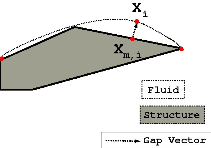
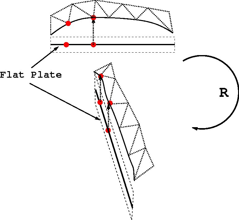
For non-matching fluid/structure meshes with non-coinciding geometric interfaces, there always exists gaps at the interface due to the difference in resolution of the fluid and structure meshes. This is shown in Figure 3. These gaps must be considered when employing a mesh motion scheme in order to maintain the integrity of the meshes (i.e. prevent element interpenetration). For example, Figure 4, shows the rotation of a flat plate when the gaps at the structure-fluid interface are not taken into account. The fluid nodes at the interface undergo the same displacements as the nodes at the structure interface. Thus, the application of a large rotation will eventually lead to element cross over. It is necessary to apply the rotation to the gap vector as well in order to maintain the mesh integrity as shown in Figure 5.

Figure 3: Fluid-Structure Interface

Figure 4: Flat Plate Rotation w/o Gap Vector

Figure 5: Flat Plate Rotation w/ Gap Vector